Description
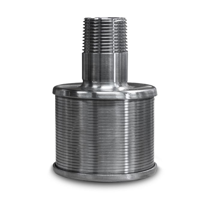
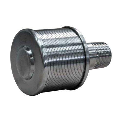
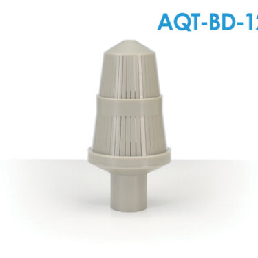
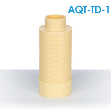
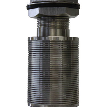
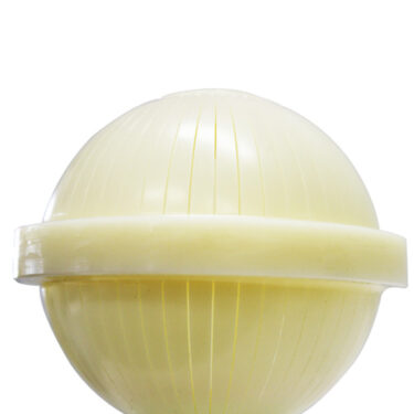
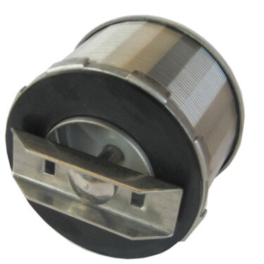
Johnson type micro-slotted nozzle to operate with flow from outside to inside, with 1″ and ¾” nipple for water filters.
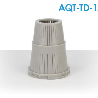
Johnson type E-I Nozzles are placed at the base of granular media beds used in water treatment.
The purpose of these means may be:
- Filtering (sand, zeolite, anthracite, garnet…)
- Purify by physicochemical changes (activated carbon, softening resin, green sand, calcite…).
In addition to retaining the medium directly, the nozzles must have sufficient capacity to collect the flow of water to be treated, distribute it uniformly in the equipment and avoid dead zones and wall effects. This depends not only on the nozzle design, but also on the correct distribution of the nozzles.
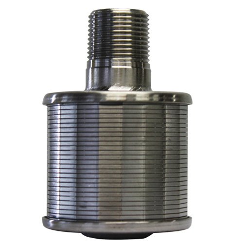
Microgrooves.
Microgrooves help to achieve good drainage and proper flow distribution.
NPT thread.
The standard NPT thread is compatible with 3/4″ connections.
316 stainless steel.
Due to their application in the food and beverage industry, they are manufactured in type 316L stainless steel.
Johnson E-I nozzles are used in both pressure and gravity operated equipment.
They are manufactured in stainless steel AI-316L in order to have chemical resistance against corrosive water and against disinfection processes carried out by means of oxidizing chemicals.
Not only are the materials of construction of this nozzle of high quality; so is the welding, which is applied by robotic means to ensure optimum strength of the final product.
An additional advantage of this manufacturing material is that it has the thermal resistance that allows disinfection by means of steam.
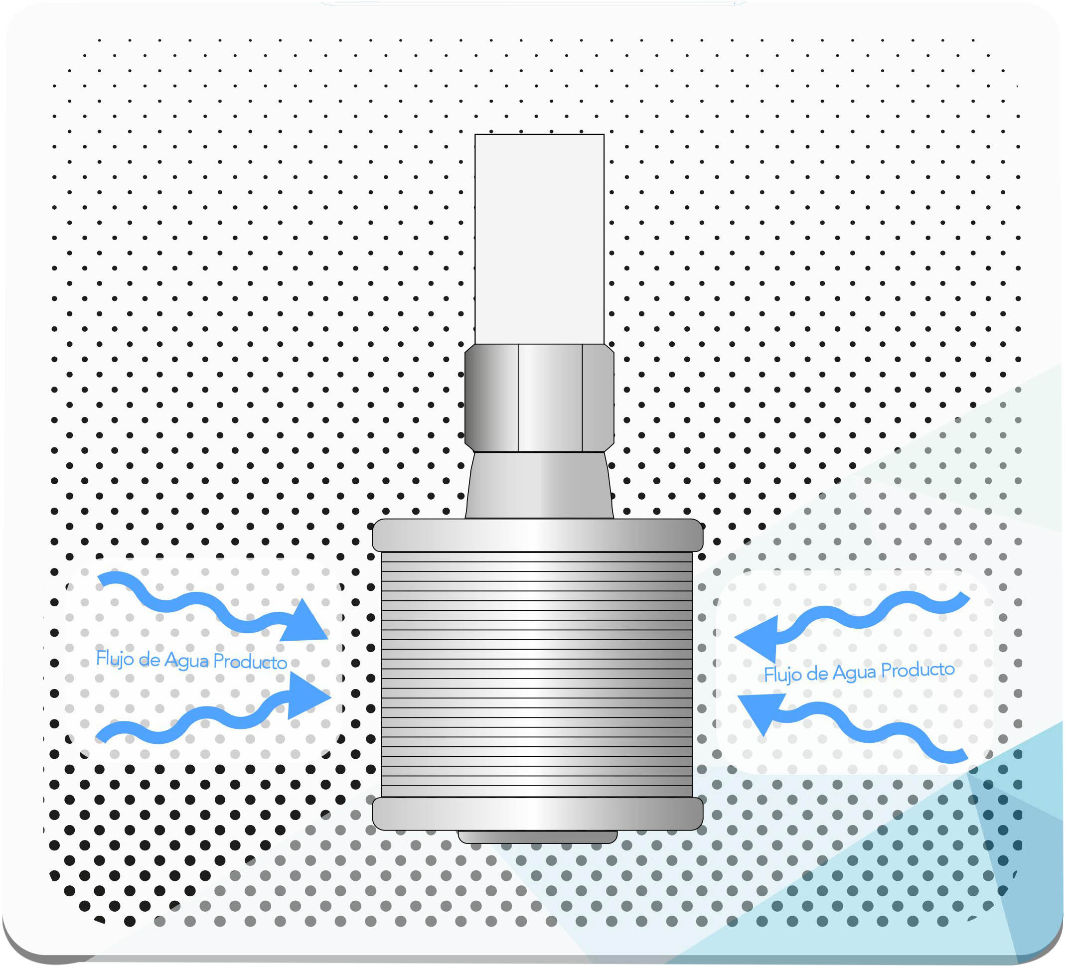
These nozzles are designed to operate with flow going from the outside to the inside of the nozzles. Nozzles designed to operate with flow from the inside to the outside are also available (if required, please request).
The Johnson E-I Nozzle is designed to cause a low pressure drop in the flow it treats.
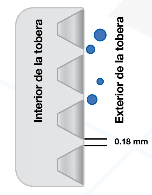
The slot through which the liquid flows has a “V” shape with the most closed part towards the outside of the nozzle. If a particle enters the slot and gets stuck, it only has contact with two edges and not with two walls. This facilitates their removal through the same operation flow or in the backwash cycle.
Schematic showing the “V” shaped slot
In the above sketch, please put a sign on the left side of the drawing that says “Inside of the nozzle” and one on the right side of the drawing that says “Outside of the nozzle”. It would be nice if the diamonds were illuminated in metallic color.
The opening of the slot is 0.18 mm in the most closed part (the one facing the outside), so this nozzle can directly retain granules larger than twice that size. That is, it can retain particles larger than 0.36 mm (corresponding to the U.S. standard 45 mesh).
If a granular media with particles smaller than 45 mesh is to be placed (for example, a media with a 20 x 50 range, with particles between 0.297 mm and 0.841 mm), it is necessary to place a gravel bed of 1/8” x 1/16“The granular media is supported by a 3” height above the nozzles and serves as a support for the granular media.
The free area for flow through the micro-slit is greater than the area of the orifices found in the part of the nipple that is inside the nozzle, and than the cross-sectional area of the connecting nipple. Therefore, it does not represent a capacity limit for the nozzle.
Specifications
| Material of manufacture | |
| Material | AI 316L stainless steel |
| Average dimensions | |
| Total length of nozzle, including connection nipple (mm) | 92.4 |
| Length corresponding to the micro-slotted element | 40.8 |
| Nominal diameter of connection nipple (in) | 1 (3/4) |
| Inner diameter of the connection nipple (mm) | 26.7 (20.7) |
| Connection nipple thread type | NPT |
| Outside diameter of micro-slotted element (mm) | 58.0 |
| Inner diameter of micro-slotted element (mm) | 52.7 |
| Number of circles making the groove in the microgrooving element | 25 |
| Slot opening on the outer face of the microgrooved element (mm) | 0.18 |
| Area of the micro-slot opening to the outside (cm2) | 8.20 |
| Percentage of free opening area for flow1 (%) | 85.74 |
| Free area for flow, from the slot opening to the outside (cm2) | 7.03 |
| Area of all orifices in the part of the nipple inside the nozzle (cm2) | 14.34 (7.85) |
| Internal cross-sectional area of connection nipple (cm2) | 5.60 (3.37) |
Note 1: This is because the nozzle has internal support posts that block part of the free area for flow.
| Nozzle distribution and operating conditions | |
| Maximum recommended distance between the center of two nozzles (in) | 12 |
| Maximum recommended area covered by each nozzle (ft2) | 1 |
| Maximum recommended service flow rate per nozzle (gpm) | 4.0 |
| Maximum recommended backwash flow per nozzle (gpm) | 6.5 |
They are manufactured under rigorous quality standards and the material of construction is 316 food grade steel.
Specifications:
- Suggested maximum service flow: 4 GPM (15 LPM)
- Suggested maximum backwash flow: 6.5 GPM (25 LPM)
- Pressure collapse: 300 PSI (2070 kPa)
- Burst pressure: 200 PSI (1380 kPa)
- Placement distance between each nozzle:
- Optimum: 15 cm.
- Maximum: 30 cm.
Learn more nozzles here:
What is a Nozzle and how does it work?
Selection of a distributor or nozzle for a deep bed filter
https://carbotecnia.info/?s=tobera
Learn more about nozzles here: https://www.filtrashop.com/?s=tobera&post_type=product
Image representative of the operation
