Description
Catalyst systems to reduce iron and manganese in water, in addition to H₂S.
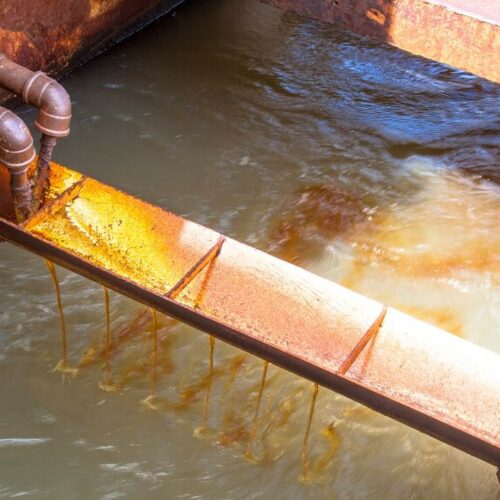
Catalysts to reduce iron and manganese in water have become more important over time and, in recent years, their use has been increasing. In some geographic regions, naturally occurring water contains iron, manganese or hydrogen sulfide H₂S. These three contaminants react with any type of oxidants and precipitate as they oxidize.
The oxidation reactions between these compounds take place slowly, and catalysts are used to combat this problem. Remembering, a catalyst is a substance that increases the speed at which a chemical reaction takes place, in some cases it can be regenerated and recovered at the end of the reaction.
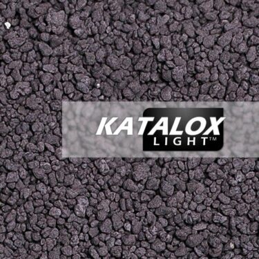
One of the most commonly applied catalysts for the aforementioned contaminants is manganese dioxide (MnO2), normally found in solid form, in the form of granules and with a purple to black coloration.
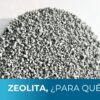
The catalysts in this range offered on the market can be pyulosite (MnO2 mineral in its natural state) or a substrate (sand, zeolite) impregnated with the same dioxide. Pyulosite has the advantage of having a higher dioxide content (surface and interior), which makes it a more expensive option.
It should be noted that not all MnO2 impregnated methods tolerate all oxidants, so attention should be paid to the specifications of the catalyst to be used.
Table for selection of catalyst systems according to their characteristics.
| Code | Tank size (in) | Bed volume (ft3) | Service flow for drinking water treatment (gpm) | Backwash flow (lpm) | Backwash flow (gpm) | Valve | Input/Output Connections (in) | Connections Drainage (in) |
Manual catalytic equipment |
||||||||
| P_650001 | 9 x 48 | 1 | 1.1 – 1.9 | 36.71 | 9.7 | F1 Model | 1 | 1 |
| P_650002 | 10 x 54 | 1.5 | 1.6 – 2.8 | 45.42 | 12 | F1 Model | 1 | 1 |
| P_650003 | 12 x 52 | 2 | 2.1 – 3.7 | 65.48 | 17.3 | F1 Model | 1 | 1 |
| P_650004 | 13 x 54 | 2.5 | 2.7 – 4.7 | 76.84 | 20.3 | F1 Model | 2 | 2 |
| P_650005 | 14 x 65 | 3 | 3.2 – 5.6 | 88.95 | 23.5 | Model F2 | 2 | 2 |
| P_650006 | 16 x 65 | 4 | 4.3 – 7.5 | 116.20 | 30.7 | Model F2 | 2 | 2 |
| P_650007 | 18 x 65 | 5 | 5.3 – 9.4 | 147.24 | 38.9 | Model F2 | 2 | 2 |
Catalytic equipment with premium Clack valves |
||||||||
| P_650008 | 9 x 48 | 1 | 1.1 – 1.9 | 36.71 | 9.7 | Clack WS1 | 3/4 | 3/4 |
| P_650009 | 10 x 54 | 1.5 | 1.6 – 2.8 | 45.42 | 12 | Clack WS1 | 1 | 1 |
| P_650010 | 12 x 52 | 2 | 2.1 – 3.7 | 65.48 | 17.3 | Clack WS1 | 1 | 1 |
| P_650011 | 13 x 54 | 2.5 | 2.7 – 4.7 | 76.84 | 20.3 | Clack WS1.25 | 3/4 | 1 |
| P_650012 | 14 x 65 | 3 | 3.2 – 5.6 | 88.95 | 23.5 | Clack WS1.25 | 3/4 | 1 |
| P_650013 | 16 x 65 | 4 | 4.3 – 7.5 | 116.20 | 30.7 | Clack WS1.25 | 1 1/4 | 1 |
| P_650014 | 18 x 65 | 5 | 5.3 – 9.4 | 147.24 | 38.9 | Clack WS1.5 | 1 1/2 | 1 1/2 |
| P_650015 | 21 x 62 | 7 | 7.5 – 13.1 | 200.23 | 52.9 | Clack WS1.5 | 1 1/2 | 1 1/2 |
| P_650016 | 24 x 72 | 10 | 10.7 – 18.7 | 261.54 | 69.1 | Clack WS2/QC | 2 | 2 |
| P_650017 | 30 x 72 | 15 | 16 – 28.1 | 408.78 | 108 | Clack WS2H | 2 | 2 1/2 |
| P_650018 | 36 x 72 | 20 | 21.4 – 37.4 | 588.57 | 155.5 | Clack WS3 | 3 | 3 |
| P_650019 | 42 x 72 | 30 | 32.1 – 56.1 | 801.28 | 211.7 | Clack WS3 | 3 | 4 |
Catalytic equipment with electromechanical valves |
||||||||
| P_650020 | 9 x 48 | 1 | 1.1 – 1.9 | 36.71 | 9.7 | AQT-275FT | 1 | 3/4 |
| P_650021 | 10 x 54 | 1.5 | 1.6 – 2.8 | 45.42 | 12 | AQT-275FT | 1 | 3/4 |
| P_650022 | 12 x 52 | 2 | 2.1 – 3.7 | 65.48 | 17.3 | AQT-275FT | 1 | 3/4 |
| P_650023 | 13 x 54 | 2.5 | 2.7 – 4.7 | 76.84 | 20.3 | AQT-285FT | 1 | 3/4 |
| P_650024 | 14 x 65 | 3 | 3.2 – 5.6 | 88.95 | 23.5 | AQT-285FT | 1 | 3/4 |
| P_650025 | 16 x 65 | 4 | 4.3 – 7.5 | 116.20 | 30.7 | AQT-285FT | 1 1/2 | 1 |
| P_650026 | 18 x 65 | 5 | 5.3 – 9.4 | 147.24 | 38.9 | AQT-285FT | 1 1/2 | 1 |
| P_650027 | 21 x 62 | 7 | 7.5 – 13.1 | 200.23 | 52.9 | AQT-315FT | 2 | 2 |
| P_650028 | 24 x 72 | 10 | 10.7 – 18.7 | 261.54 | 69.1 | AQT-315FT | 2 | 2 |
Components of a catalytic filter to remove hydrogen sulfide H₂S, iron and manganese.
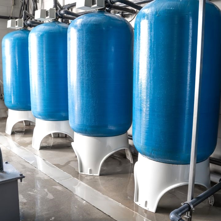
- Fiberglass tank.
Made as a single piece, its interior is made of polypropylene coated with fiberglass, which adds mechanical resistance. Its maximum operating pressure is 150 psi.
- Automatic valve.
Raw water passes through it to reach the catalyst bed. It has its respective inlet, outlet and drainage connections. It allows the change of service or backwash positions, this through a time-based programming. Similar to the tank, its maximum operating pressure is 125 psi.
- Catalyst.
Granular medium.
- Upper and lower distributor and distribution pipe.
The distributors allow a better flow distribution during backwashing, thanks to their micro-slotted structure. In addition, it acts as a barrier to prevent the leakage of granular media into the outlet line.
On the other hand, the central distribution pipe is a Schedule 40 PVC pipe that connects the distributors to the valve.
- Supporting gravel.
The tank contains silica gravel of 1/8 x 1/16 mesh backing. The micro-grooved distributor avoids the placement of several gravel beds of different grain size.
Advantages of catalytic equipment.
Some of the advantages offered by catalytic equipment to reduce iron and manganese are:
- High capacity to store oxidizing compounds on its surface, which allows intermittent regeneration. With this it is not necessary to add oxidant continuously, since the catalyst can provide it as it works.
- They allow the use of backwashes to remove (from time to time) the particles that clog the pores of the medium.
- They have a life span of approximately 7 to 10 years.
Design of catalytic systems.
For the design of equipment with granular media that cause a physicochemical change (catalysts, for example) it is important to take into account the variables of contact time in empty bed (TCCV) and the service flow rate (not too high to avoid pressure drop and erosion of the medium, and not too low to affect mass transfer).
For the empty bed contact time for iron and manganese as contaminants, the following equation can be used, which shows the total concentration from that of iron and manganese:
C = [Fe+2] + 2[Mn+2]
Where:
- If C < 5, recommended TCCV of 4 min (not less than 3 min).
- If C = 5 to 10, recommended TCCV of 7 min (not less than 4 min).
- If C = 10 to 30 min, two tanks connected in series, each with TCCV of 7 min.
- If C > 30, the case needs to be analyzed in more detail, as the proposed treatment may require more detail.
For the service flow rate, they are usually proposed:
- 10 to 20 m/h (4 to 8 gpm/ft2).
- 7 to 10 m/h (3 to 4 gpm/ft2) in cases of high pollutant concentrations.
*Suggested articles:
Z-OX For manganese and iron removal in water – Carbotecnia
Iron and manganese removal methods – Carbotecnia
Iron, manganese and hydrogen sulfide catalysts. (carbotecnia.info)

